|
The Journal of |
| Section 1 | Editors Introduction |
|
Richard Wood-Roe |
In this issue of The Journal we have included an update to the IPC alert about microvia reliability from Happy Holden. There is a paper outlining the optimisation of process parameters for microvia processing from Bill Bowerman of Alpha Macdermid. Daniel Schulze of Dyconex has provided a fascinating contribution detailing the benefits of thin materials for space saving and reliability. Computer Aided Engineering Simulation for Production Proofing PCB Copper Plating is the subject of a paper from Robrecht Brelis of Elsyca. We are grateful to Pete Starkey for his write up of the recent ICT evening seminar that was held in Meriden, West Midlands. In the members news section we report on the sad passing of Bill Miller, a founding father of the UK PCB industry. The members update section shows a large increase in members from the successful on-line engineering course. This course will be available again soon via our web site. Finally the industry news section highlights the activity of some of our members. |
| Go back to Contents |
| Section 2 | Calendar of Events | |
Bill Wilkie |
2023 |
Details |
| March 7th | ICT AGM and Spring Seminar at Meriden. Council Meeting – Starts at 12 noon, Fab Group Meeting starts at 14:30, AGM/Seminar starts at 18:00 – to be followed by a buffet. Manor Hotel Room Rate - £100/night B&B at ICT Rates |
|
| April 24-27th | Annual Foundation Course, Chester | |
| 2022 | ||
| Nov 29th | Evening Seminar at Meriden Preceded by Council Meeting and Fabricator Meeting. | |
|
September 7, 14, 21, 28 and October 5, 12, 19, 26 |
On-line Engineering Training with Happy Holden. Each session is from 4pm to 5pm | |
| Go back to Contents | ||

| Section 3 |
IPC Warning About Microvia Reliability for High Performance Products Editors Note: It is recognised that this alert was issued some time ago but it has been included in this issue of The Journal to ensure that members who may have missed it are informed. |
 Happy Holden Happy Holden |
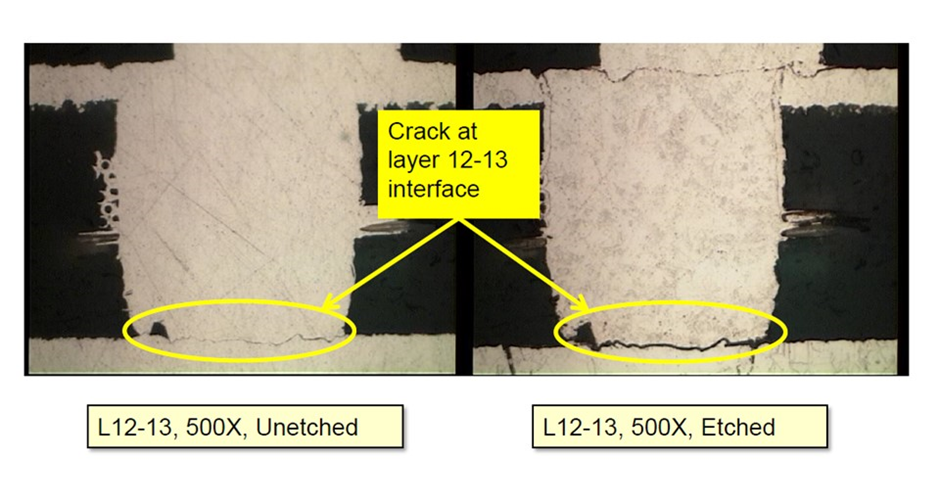
Hopefully, by now, you have read the full Press Release from the IPC on March 6, 2019, about the warning of field and latent failures of high-profile HDI boards. IF not, the complete press release is available on I-Connect 007. [1] DON’T PANIC! Let me explain the background of this warning. For the last few years, a few OEMs have experienced a latent defect in their sophisticated HDI multilayers even though screened with our best available incoming inspection and test methodologies. This defect caused failures observed in: • Post-Reflow In-Circuit Test After much work and investigations by these OEMs, and with coordination with the D-32 Thermal Stress Test Methodology Subcommittee, the IPC issues a new test method for thermal stress, (IPC-TM-650, Method 2.6.27A) and thermal shock (IPC-TM-650, Method 2.6.7.2). The Method 2.6.27 calls for the test vehicle or coupon to be subjected to a normal solder paste reflow profile to reach a peak temperature of 230 degree C or 260 Degree C while under connection to a 4-wire resistance measuring unit for six (6) full reflow profiles without the increase of resistance of 5%. The daisy chain in the test coupon needs to be composed of features used in the actual circuits. This has allowed these OEMs to detect the latent microvia failures and protect themselves from possible defect escapes. But finding the Root Cause of this latent HDI failure has been elusive. So, in early 2018, the IPC organized a select group of industry experts, under the supervision of Michael Carano, to investigate this situation. Later in 2018, this group was named the IPC V-TSL-MVIA Weak Interface Microvia Failure Technology Solutions Subcommittee. I am a founding member of this group. But let me emphasize, During the past year, we have met and gone over test data, microsections and experimental results. Here is what we KNOW: • The defect manifests itself as a fracture at the metallurgical interface of a microvia to the copper layer below it or to another microvia below it. (see Figure 1)
FIGURE 1. The WMI latent defect observed after six reflows of 230 OC. [used with permission][4] • First occurrence of the product-level failure detected (stacked microvias) 2010.
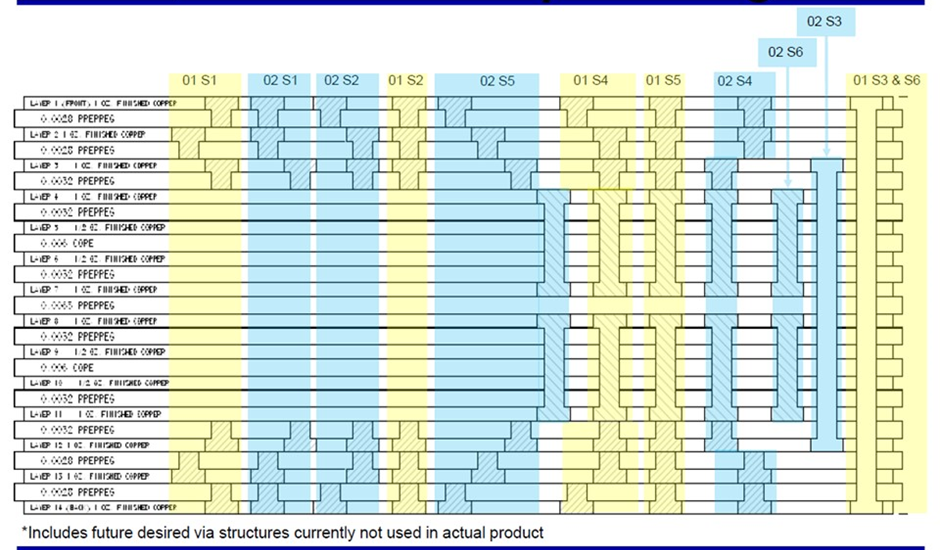
FIGURE 2. A complex HDI qualification coupon (3-8-3) with both stacked and staggered microvia structures. [used with permission] [4] • Product-level failures are unpredictable (in-process, storage or filed)
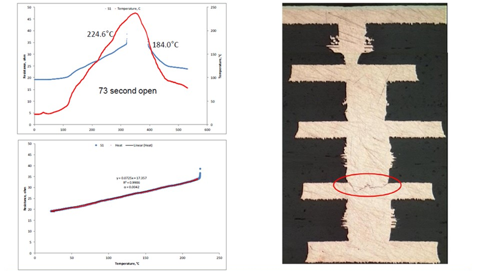
FIGURE 3. Reflow profile and 4-wire resistance of a 4+N+4 stacked microvia structure opening at only 224.6C and closing at 184C on cooling down. Subsequent room temperature testing and thermal cycling testing indicated no defect. [used with permission] [4] • Although the committee developed an FMEA for microvia defects, only this one WMI is our focus. To further read about the WMI Committee and our findings, there is a report available from our APEX 2019 WMI OPEN FORUM[2] and a White Paper was published by the committee, IPC WP-023 “Via Chain Continuity Reflow Test: The Hidden Reliability Threat- Weak Microvia Interface.” Available from the IPC Bookstore. REFERENCES |
| Go back to Contents |
| Section 4 | Process Improvement Strategies for Weak Microvia Interfaces
William Bowerman, Jordan Kologe, Rich Bellemare and Warren Kenzie MacDermid Alpha Electronics Solutions |
|
Bill Bowerman |
Abstract
Figure 2 – UV-CO2 laser drilled microvias shown after shown after UV clean, plasma, and desmear.
Figure 4 – 2 Level DOE results for UV clean, desmear cycle, and flash plating impact on 50x reflow failure rate.
Figure 5 – Top, main effects plot for solution movement DOE. Bottom, copper grain structure at base of target pad rating system examples.
Figure 6 – Top: Experimental results that display the effect on microvia aspect ratio and diameter on grain structure quality. Bottom: Example of plated electroless copper at the via target pad and the rating of grain structure.
Figure 7 – Study: Adjustment of the control levels for the specific gravity of the electroless copper bath for HDI. A study was done, selecting panels run at various sites around the world to see the effect the grain structure had on simulated reflow testing per IPC 2.6.27. Figure 8 shows the electroless copper grain structure at the via target pad for the various sites A-E. The same electroless copper formulation was run at different sites for A, B, C and D. Site E was a different electroless copper formulation. Sites A and B show the ideal angular grain structure. Sites C and D show a dense structure but not ideal. Site E appeared porous and cauliflower like. Sites A and B passed 24 OM cycles as the censor point while the other panels had some level of failures before 24 cycles.
Figure 8– Electroless copper grain structure plated at various sites around the world.
Figure 9 – Etch chemistry impact on roughness and topography of the underlying substrate.
Recrystallization had formed a continuous grain structure indicating strong layer to layer bonding. Lack of recrystallization across the various copper interfaces can be attributed to several factors. Recrystallization can be interrupted by a macro-rough surface on the target pad, from recast copper, from a layer of oxidization on any interface during metallization, dry film or developing residues, or by a non-epitaxial copper structure that did not follow the orientation of the substrate.
|
| Go back to Contents |

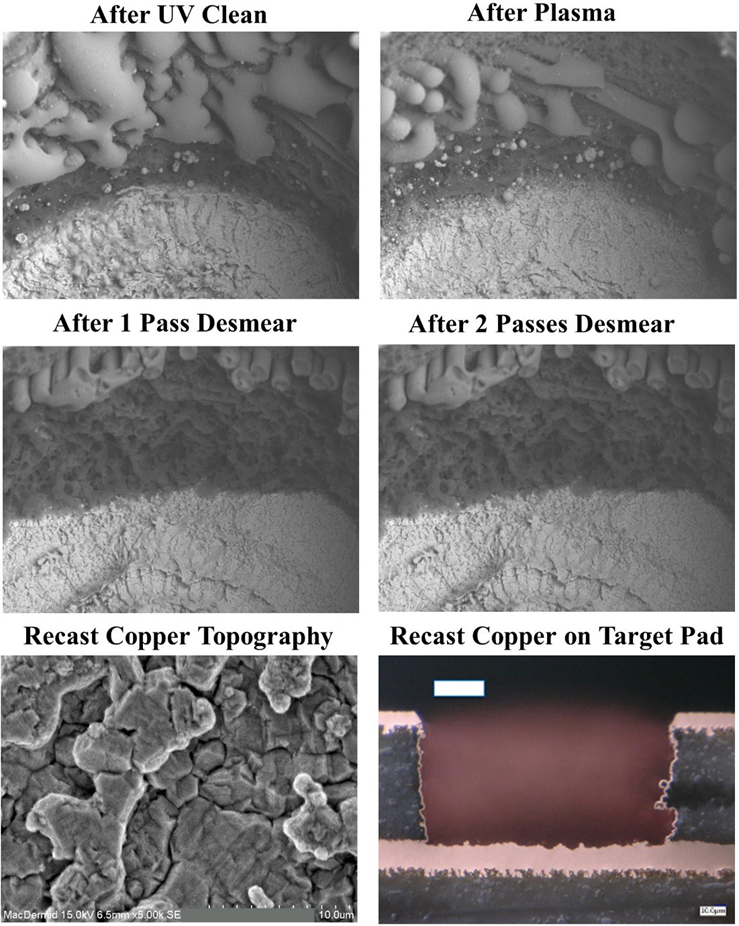 Figure 1 – UV drilled microvias shown after defocused laser clean, plasma clean, and 1x-2x desmear, recast copper macro-rough topography on un-plated target pad.
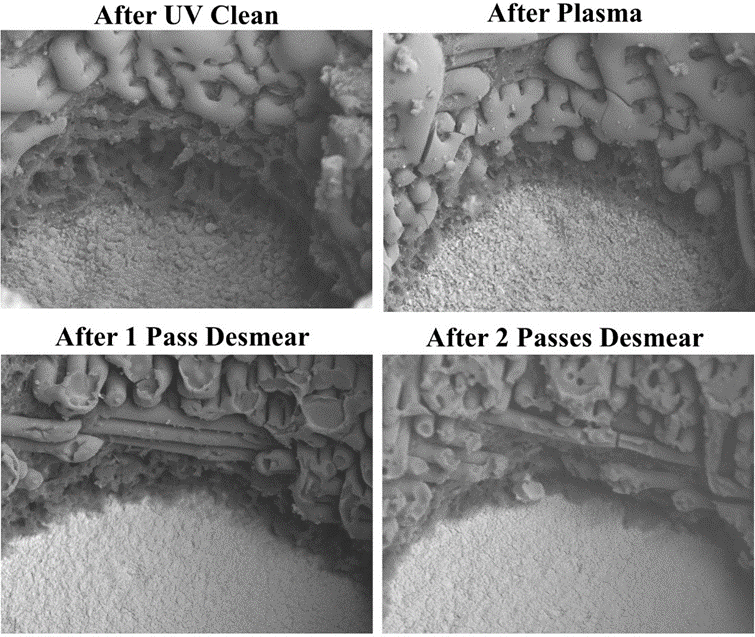
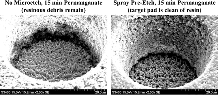 Figure 3 – The effect of chemical pre-etch on resinous debris.
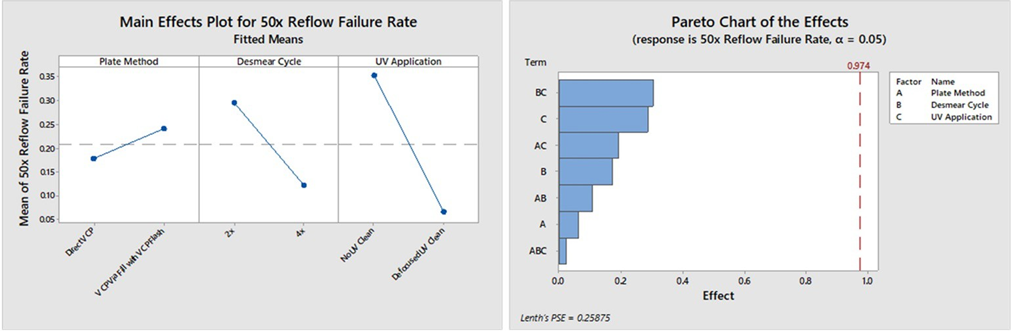
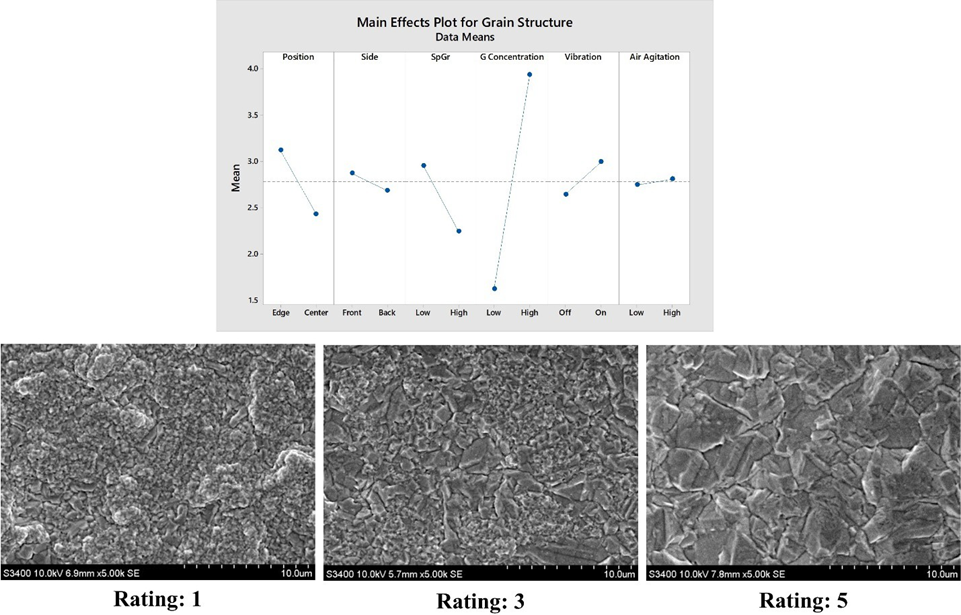

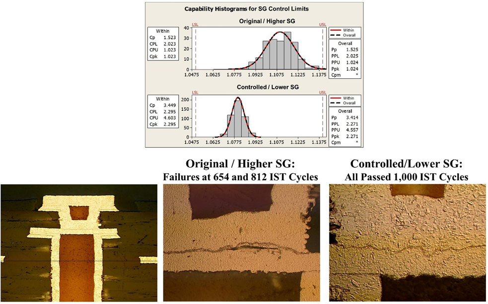
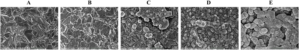
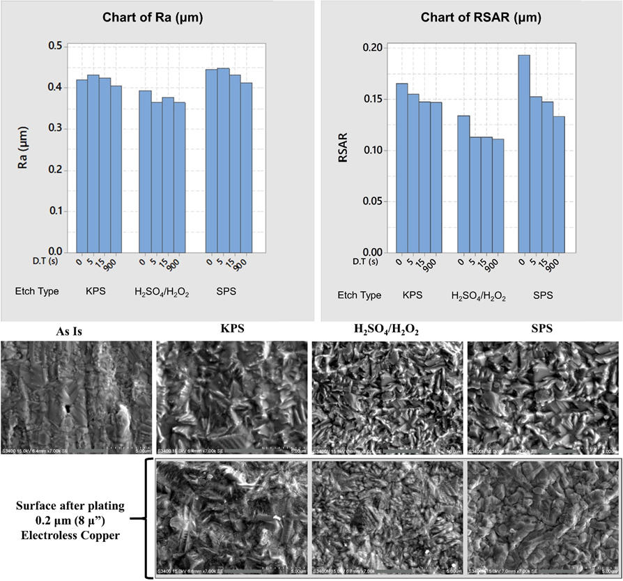
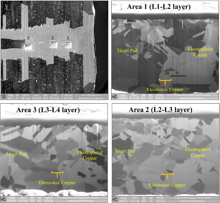 Figure 10 – 3+N+3 Stacked microvias showing continuous grain structure and strong layer to layer bonding.
| Section 5 |
Ultra Thin Base Materials Take PCB Manufacturing to the Next Level Daniel Schulze |
||||||||||||||||||||||||||||||||||||||||||||||||||||||||||||||||||||||||||||||||||||||||||||||||||||||||||||||||||||||||||||||||||||
 Daniel Schulze Daniel SchulzeApplication Engineering Manager - Dyconex |
Almost all markets are experiencing increasing demand for smaller and thinner electronic devices. Today’s mobile devices are small enough to fit in a watch, and the aerospace and automotive industries desire smaller and lighter devices to lower fuel costs and reduce emissions. Likewise, the medical industry needs wearable sensors, implantable devices, and handheld instruments that are small and lightweight. Manufacturers of the printed circuit boards (PCBs) that are at the heart of these electronic devices have been making them more compact and lighter primarily by decreasing the size of the copper features and board materials. Extremely thin base materials are making it possible to take miniaturization beyond what was previously possible without compromising reliability or performance.
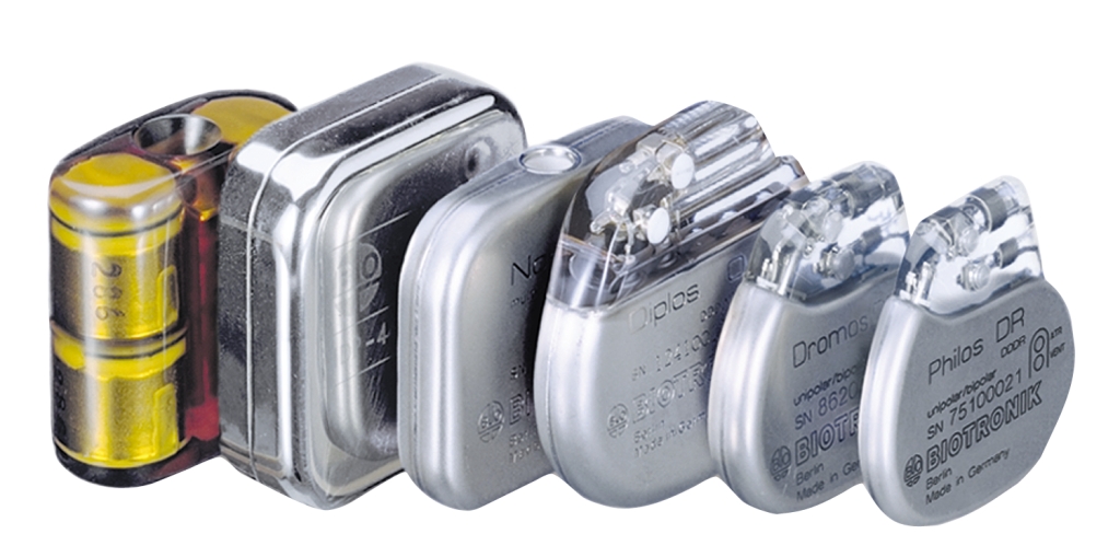
Figure 1. Evolution of pacemakers. Image courtesy of Biotronik. With thinner base materials, less plated copper is needed to fill via connections. This automatically results in thinner copper layers and, therefore, lines/spaces with smaller resolutions and a reduced interconnect footprint.
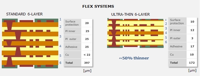
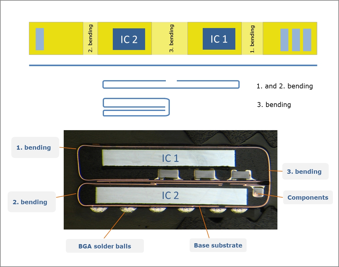
Figure 2. 6-layer stack-up with standard flex material compared to 6-layer stack-up with ultra-thin base material. Flex systems are used in hearing aids to ensure all the necessary electrical components can be housed within a package that fits in the ear canal. In this case, the circuit board is assembled flat with the integrated circuits, resistors, and capacitors and then folded to reduce the overall footprint.
Figure 3. From flat substrate to folded package. Ultra-thin flexible substrates also allow better bending. This means the PCBs can be bent with smaller bend radii to achieve even smaller volumes. A comparison is shown in Table 1. The improved bending makes ultra-thin flexible materials ideal for making cables that require dynamic bending, as in robotic arms.
Table 1. Comparison of minimum bend radii according to IPC-2223 5.2.4 Today, the outer layers of a multilayer flex system typically measure 12 µm for the polyimide and 12 µm for the adhesive. The new Flexible Resin Coated Copper (FRCC) material available offers 3 or 5µm thick polyimide outer layers combined with a minimum 17 µm thick adhesive layer.
Figure 4. Cu clad polyimide laminate.
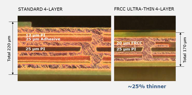
Table 2. Characteristics of FRCC materials. Figure 5. Standard 4-layer flex system vs. ultra-thin 4-layer flex system
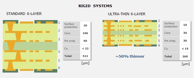
Rigid Systems Figure 6. 6-layer stack-up with standard rigid material compared to 6-layer stack-up with ultra-thin base material.
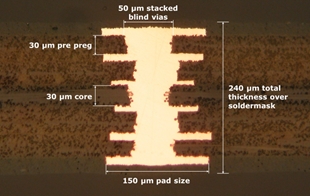
Table 3. Comparison of design features for 6-layer systems Figure 7. 6-layer rigid stack-up with ultra-thin materials. The coefficient of thermal expansion of the rigid substrate is one of the most important properties for chip packaging substrates. If it is not matched well with the silicon die, it can lead to cracks that adversely affect packaging production and the assembly of the components onto the substrate. Problems with thermal expansion can even lead to failures during device use. Ultra-thin substrate materials also need to have very good high-frequency properties to achieve the requirements of today’s high-speed telecom applications.
Table 4. Characteristics of advanced ultra-thin rigid material.
Conclusion |
||||||||||||||||||||||||||||||||||||||||||||||||||||||||||||||||||||||||||||||||||||||||||||||||||||||||||||||||||||||||||||||||||||
| Go back to Contents | |||||||||||||||||||||||||||||||||||||||||||||||||||||||||||||||||||||||||||||||||||||||||||||||||||||||||||||||||||||||||||||||||||||

| Section 6 |
Computer Aided Engineering Simulation for Production Proofing PCB Copper Plating Robrecht Belis, Elsyca, Belgium |
||
|
Robrecht Belis |
Maximizing production yield is vital for PCB manufacturing.
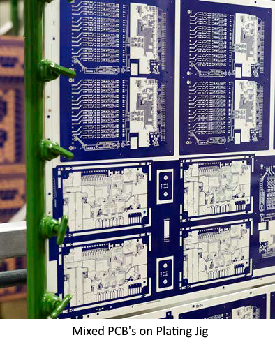
PCB Layout before and after copper balancing (Right picture – black areas represent added dummy copper features) Existing DFM tools do not allow to assess finished copper thickness CAE simulation technology empowers designers to optimize PCB copper plating Predicted copper distribution before and after optimisation During the electroplating process, the PCB substrate is submersed in a tank with an electroplating bath and anodes. As direct current always seeks the path of least resistance between the anodes and the cathode, PCB edges and areas with a sparse active copper surface attract more than their fair share of current compared to areas with a high number of traces, through-holes, vias or pads. Due to this current crowding effect, more copper deposits onto the PCB along its edges and in areas with a sparse active copper surface. That explains why finished copper thickness typically shows an unwanted variation across the circuit board. No two pcb's are produced the same way Even if a PCB panel only contains identical board designs, the copper plating process does not deliver the same finished copper thickness for each PCB. Copper balancing reduces differences between circuit boards on the same panel. To mitigate this problem, CAM engineers can modify the panel layout, or they can apply copper balancing to thieve current from areas that attract more than their proper share of current. Adding dummy copper features near the panel edges and in between individual boards achieves a more uniform distribution of finished copper thickness across the entire panel. Auto-intelligent copper balancing lets PCB manufacturers deliver better boards at a lower cost.
Ultimately, CAE simulation lets CAM engineers deliver a better service to production. In particular, product testing can focus its resources on the most critical elements. CAE simulation technology also allows process engineers to fine-tune copper plating production settings.
Typical PCB Electroplating Line Elsyca, Belgium Tel: +32 16 474960 |
||
| Go back to Contents |

 Starting from a graphical overview of the finished copper thickness distribution over the entire PCB panel, CAM engineers can easily assess any critical areas that remain and advise the production team which PCBs need testing and which areas these tests should focus on. That applies in particular to vias and through-holes, where the presence of a sufficient copper thickness is a critical quality indicator.

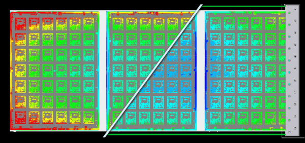
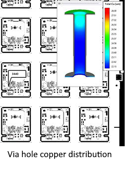 Simulation provides a graphical overview of the finished copper thickness distribution over the entire PCB panel. This overview enables CAM engineers to identify potential plating issues upfront and assess the most critical areas. As a result, they can inform the production team which PCBs need testing and which areas should these tests should focus on. They can identify particular vias and through-holes, where the presence of a sufficient copper thickness is a critical quality indicator.
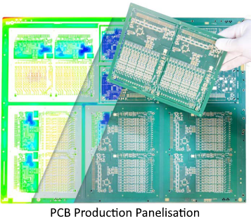 Using a digital twin of their in-house PCB plating tank, simulation enables process engineers to finish the work set in motion by PCB designers and CAM engineers. They can run in-depth what-if analyses and explore various scenarios for fine-tuning copper plating production settings. Possible what-if analyses include verifying the impact of layout modifications (such as the spacing in between individual panels), tooling (such as shielding, current robbers or auxiliary anodes), and process parameters (such as changes in imposed current density and total process time). And process engineers can do all of this without running any time-consuming trials in a real-world production environment.
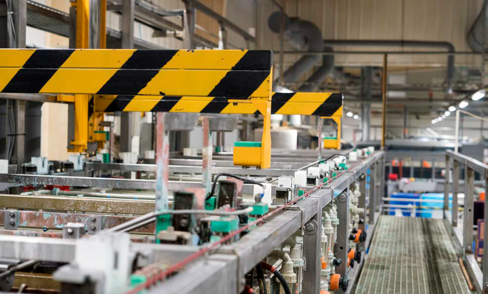
 Regardless of the potential distraction of the international football match between England and Wales in the World Cup competition, an enthusiastic crowd of PCB fans gathered in Meriden UK for the Institute of Circuit Technology Christmas Seminar, an eagerly-awaited networking opportunity that included a face-to-face industry welcome event and an outstanding technical programme.
 Using video clips for illustration, McMaster described selective soldering as a process where individual through-hole components are soldered onto a PCB using a solder fountain programmed to move to each required position from underneath the assembly. The principal benefit of using a single-tube nozzle during this process is that each solder joint can be independently controlled with minimal thermal shock. This highly flexible non-contact process results in fewer solder defects.
 Kiratzis discussed innovative solutions for EV battery modules, including flexible circuit applications for voltage and temperature control, and the manufacture of intelligent cell contacting systems for interconnection of individual cells within battery modules. He explained that, as a supplier to the automotive industry, the production part approval process is always a key consideration for the company. This industry standard outlines the process for demonstrating that engineering design and product specifications can be consistently met by the supplier's manufacturing process. Critical elements include accurate design records; a defined, monitored, and controlled process; and complete record-keeping and procedures for process failure mode effects analysis.
 Bodegom began with some industry statistics and forecasts: The value of the global PCB market totaled $70.92 billion in 2020, of which the flex component doubled from 8% to 17% in recent years; the market is projected to reach a total of $86.17 billion in 2026 and as much as $130 billion by 2030. But although 93% of all production is currently coming from Asia, there is a clear trend toward increasing production in the U.S., followed by Europe. However, this shift will only happen if Europe makes a committed investment in greater automation in both hardware and software. Introducing and retaining intelligence throughout every stage of the manufacturing process is critical if Europe is to achieve better overall process control and alignment of different processes, with an aim toward higher traceability and self-learning algorithms.
 Trackwise’s key markets are in the automotive, aerospace, medical and scientific & industrial sectors. In automotive applications, flexible PCBs are suited to EVs in battery modules, battery packs, and battery management systems. Examples include 6-ounce copper weights, which can carry high-voltage power. In aerospace, large-scale flex (LSF) offers a 70% to 90% weight reduction in data cables and a 10% to 20% weight reduction in power cables. They can be used for fuselage-length or full-wing-width interconnects and are qualified for high temperature operation in harsh environments. At the other end of the scale, long, ultra-flexible, and finely-etched printed circuits have become key enablers for catheter-based distal electronics, with tracks and gaps as small as 50 microns.
 Driver acknowledged that the Institute of Circuit Technology has always been an effective platform for launching new ideas. His challenge was how to change the mind-set: “Everybody always wants to talk about what things can’t do. I’m an optimist and try to make everything positive. This might not become commercially viable within our lifetime, but it could be just the start of something good!” He called on the industry to engage with the Jiva philosophy and to cultivate a “It might just work” mindset.
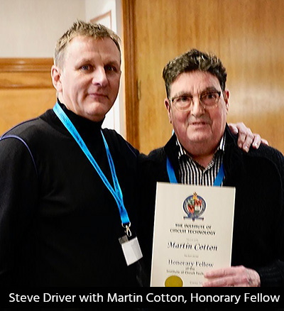 A very welcome seminar delegate was Martin Cotton, long-term supporter of the Institute and regular past presenter, who was determined to attend while continuing his slow recovery from serious illness. Everyone was delighted to see him and showed their sincere appreciation as he was awarded an Honorary Fellowship.
|
Members News |
|
|
Bill Miller - Prestwick Circuits Ltd.
Bill has already had an obituary placed in the Times Newspaper, but as a Fellow of the Institute, (Membership Number 556), it is fitting that we include our own thoughts in our Quarterly Journal. The Times obituary is available here. |
|
|
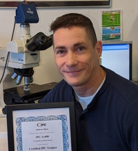
Andrew Bunt |
IPC CIT Certification Andy Bunt is a now a Certified IPC-A-600 Trainer and will start an internal training programme for employees soon. We would like to congratulate Andy for his work achieving this certification. |
|
|

|
Industry News |
|
| Adeon Technologies BV |
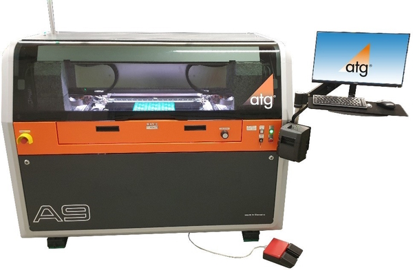
ACB Group invests in new Flying Probe System
The ACB group is one of Europe’s largest independent manufacturers of highest technology printed circuit boards. The group consists of manufacturing facilities at Dendermonde (Belgium), Atlantec and Cibel (France) Read more... |
| Amphenol Invotech | Environment and Sustainability An interview with Hannah Whitmore Amphenol Invotec’s new Head of Environment and Sustainability Read more... |
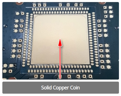
| GSPK Circuits | Innovative Copper Coin Thermal Solution A copper coin is a solid piece of copper that is put onto or into the PCB, usually beneath the component or components that require cooling. When compared to a collection of thermal vias copper coins will produce roughly twice the cooling. Additionally, the copper coin can offer direct contact between the heat-generating component pad and the heat sink in place of thermally conductive material. Compared to other conductive dielectric prepregs, copper has thermal conductivity that is typically 50–200 times better. Read more... |
| Minnitron Ltd. |
Family Business Awards |
| Newbury Electronics Ltd | Managing Director of Newbury Innovation Conor La Grue, has been appointed to the position of Managing Director of Newbury Innovation, the design division of Newbury Electronics Ltd.  Newbury Innovation has grown significantly over the last 3 years and is now a major business unit within the Newbury Group. Read more... |
| Southern Manufacturing | Southern Manufacturing & Electronics show will be held from 7-9 February 2023 The annual Southern Manufacturing & Electronics show is a firm favourite on the calendar. Aerospace Manufacturing takes a closer look at what visitors can expect to see at the Farnborough Exhibition Centre from 7-9 February 2023. |
| Taiyo |
Taiyo Circuit Automation European Distributor for Shur-Loc Products Taiyo Circuit Automation today announced a new partnership with Shur-Loc Fabric System. This partnership will combine Taiyo Circuit Automation world renown range of solder mask equipment with Shur-Loc’s unique screen making system. Read more... |
| Trackwise Designs plc | Quality Assured at Trackwise Designs plc Trackwise is delighted announce the successful completion of their AS9100/ISO9001 surveillance audit. The surveillance audit is a biannual process where the QMS processes are audited. This is to demonstrate “the ability to consistently provide products and services that meet the customer and regulatory requirements” Read more... |
| Ventec International Group |
High Thermal Conductive Metal Base Laminate |
| Go back to Contents |

Membership News |
||||||||||||||||||||||||||||||||||||||||||||||||||||||||||||||||||||||||||||||||||||||||||||||||||||||||||||||||||||||||||||||
|
|
New Corporate Members
|
|||||||||||||||||||||||||||||||||||||||||||||||||||||||||||||||||||||||||||||||||||||||||||||||||||||||||||||||||||||||||||||
|
New Member
|
||||||||||||||||||||||||||||||||||||||||||||||||||||||||||||||||||||||||||||||||||||||||||||||||||||||||||||||||||||||||||||||
|
New Associate Members
|
||||||||||||||||||||||||||||||||||||||||||||||||||||||||||||||||||||||||||||||||||||||||||||||||||||||||||||||||||||||||||||||
| Go back to Contents | ||||||||||||||||||||||||||||||||||||||||||||||||||||||||||||||||||||||||||||||||||||||||||||||||||||||||||||||||||||||||||||||
ICT Council Members |
|
|
Council Members |
Emma Hudson (Chair), Andy Cobley (Past Chairman), Steve Payne (Hon Deputy Chairman), Chris Wall (Treasurer), William Wilkie (Technical Director, Hon Sec, Membership & Events), Richard Wood-Roe (Journal Editor & Web Site), Jim Francey, Martin Goosey, Lynn Houghton, Lawson Lightfoot, Pete Starkey, Francesca Stern and Bob Willis, |
Editors NotesThe ICT Journal |
|
|
Richard Wood-Roe |
Instructions / Hints for Contributors 1. As it is a digital format the length is not an issue. Short is better than none at all! 2. Article can be a paper or a text version of a seminar or company presentation. Please include data tables, graphs, or powerpoint slides. We can shrink them down to about quarter of a page. Obviously not just bullet points to speak from. 3. Photo's are welcome. 4. We would not need source cross references 5. Title of presentation - Of course! Date, Job title of Author and Company represented. 6. An introductory summary of about 150 words would give the reader a flavour of what it's all about. 7. Style - we don't want out and out advertising but we do recognise that the author has a specialism in the product or process that will include some trade promotion. Sometimes it will be a unique process or equipment so trade specific must be allowed. 8. Date and any info relating to where or if this article may have been published before. 9. We can accept virtually any format. Word, Powerpoint, publisher, PDF or Open Office equivalents. 10. Also, to make it easy, the author can provide a word file to go along with his original powerpoint presentation and I/we can merge it together and select the required images. 11. A photo of author or collaborators. I really do look forward to receiving articles for publication. Richard Wood-Roe |